


Time to Complete Mod is 15-30 Minutes
Recommended above for Ages 12
Please use parental supervisions
Requirements:
Digimon to be Modified
FX Light Mod and Installation Package
Soldering Iron and Solder
Basic Soldering Skills (Solder Wire To Pad)
28awg Wire Strippers and Cutters
Hot Glue Gun and Hot Glue
Small Philips (Star) Screw Driver to Open Digimon
Dremel with 1/16" bit to Carve/Remove Plastic
Please Follow Instruction Order Carefully
If you have any question please do not hesitate to contact support below.
Open Up the Digimon
Using the Small Philips (Star) Screw Driver
And Setting all it parts to the side

Modify the Case
A Dremel and a 1/16" bit is recommended but wire cutters can work.
Carve Plastic Away as shown below.
A Dremel and a 1/16" bit is recommended but wire cutters can work.
Carve Plastic Away as shown below.

Remove Roughly 21mm from the center of the case
and make it flush to screen and front. See close-up pictures below.
and make it flush to screen and front. See close-up pictures below.
Make sure you have removed rubber buttons and glass screen before doing cutting.

Once the Plastic Modification is complete re-place the buttons and screen back into the case.
The screen must be placed with its rounded-side of the screen facing in towards the buttons.

Clean the screen and light guides of any dust and finger prints. Fold all panels that require folding. Now place the diffuser panel texted side away from us.

Next the front reflector, shiny side facing us.

Now place the stack of 5 light guides.

Align the light guides up best as possible.


Place in the mod chip as shown. It should sit well, with a little bit of room play.

Now place the back reflector panel.

Use a very small tool or knife to help guide the reflector panel and align the panels.

Check to make sure that the backer is properly seated over top of lightguides.


Now for wiring up the Mod to the Digimon

Using two more small size stickers that we cut in the previous steps, we tape down the opposing side of the screen, to the Digimon case.

Now we will start routing the wires. Bend all wires into the place shown below. Basically all wires are tucked into the front of the case in desired locations ready to route through to the back of Digimon PCB.
The blue wire is bent to the location were it will be connected under the backlight screen on the Digimon PCB. We will work on this wire first.

Measure the blue wire to approximately 1 3/4" and cut

Strip the insulation off the blue wire

Tin the tip of blue wire. Get the Digimon PCB ready. Plug in hot glue gun to warm up.

Lay blue wire flush on Digimon PCB to proper location on the in-side of C8. Apply a very small amount of hot glue over blue wire is the shown location. Use just enough to hold the blue wire securely. Use sparingly.


Next we have to solder the connection of the blue wire to C8. Apply a quick amount of heat to the tinned blue wire, and it will melt and solder to the C8. Do not dwell here long with heat to not burn C8. Do not more apply pressure to C8 as it may become loose. Be very careful as you do want to damage the Digimon PCB or C8. See completed solder joint pictures below. (If you damage C8 or Digimon, please contact us. We can provide solutions.)


Now we can move onto mounting the Digimon PCB back, but first we must make sure the wires are routed correctly to avoid pinch points and that the lights are centered. Slide the FX light PCB so that it is centered. Follow the examples below for routing the wires.
The black wire is hard to see but it is tucked to the back at the top.
The black wire is hard to see but it is tucked to the back at the top.

Carefully place the Digimon PCB, making sure not to pull hard on the blue wire, as we do not wish to damage that connection or C8. Prepare the Digimon PCB for mounting the screws by making sure no pinch points on wires, as well keeping a small amount of each wire slack tucked into the front case as shown in previous steps.


Now that we have made sure that it is a nice fit, we will add the 4 silver screws.
When tightening the screws it is recommended to go around in an alternating pattern tightening each screw only slightly at a time. This gives even pressure on the screen contacts to the Digimon PCB.
Make sure you do not over tighten screws as they can strip in the plastic. (This can be repaired if needed. Contact us)
During tightening, you may notice something stopping you from continue to tighten, like screws are getting tight but PCB is not completely flush to case yet. Do not continue to tight as this can cause damage to possibly both the Digimon and the Light FX Mod. The problem is in alignments, a pinch point, or the FX Light Mod PCB is not sitting correctly in backlight panel configuration. Carefully lift the Digimon PCB (noting the blue wire is attached be careful) and adjust anything that is out of alignment.

Now we can get to routing and finishing the build. We will want to route the wires as shown.

First Measure each wire to there location, leave a very small amount of slack and cut wire.
Approximate lengths are below.
Red Wire - 1 3/4 inches
Black Wire - 2 3/4 inches
Green Wire - 2 1/2 inches
Yellow Wire - 2 1/2 inches
Please make sure you check your wires to the pad locations, and not just take these measurements and cut. It is better to be slightly loose on the wiring, as we can tuck some into the front casing, or back casing.
Do not cut wires short. Otherwise you will have to replace the short wire or add an extension.


Strip the ends of each wire.

Tin the tips of each wire.


Now add a tiny bit of hot glue to hold black wire to the back of the Bat + terminal spring. This helps with final case closing.

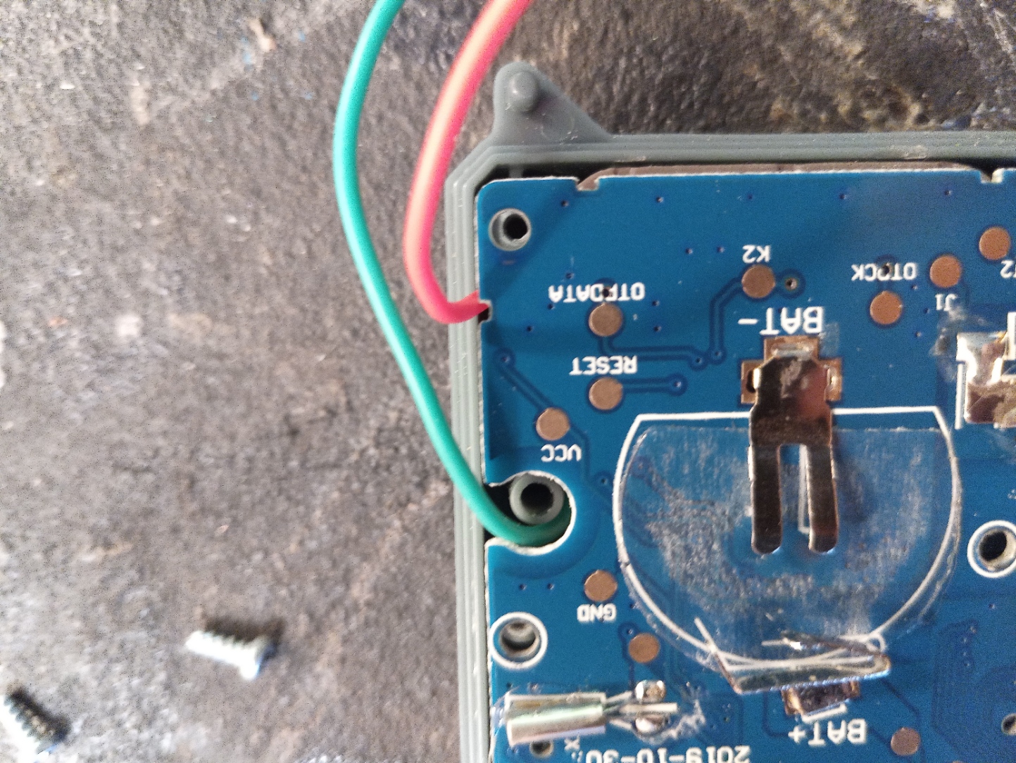
Next we apply a very small amount of solder to the Digimon PCB pads:
Capacitor +
Capacitor -
BZ-
VCC
GND
DTPDATA


Now we will solder each wire, one at a time.
Red -> VCC
Green -> BZ-
Black -> GND
Yellow -> DTPDATA
Take note of the routing positions of the wires, and follow as close as possible. As shown in the examples try to leave small amount of slack in wires, incase issues and must lift Digimon PCB again.


Next we install the 100uF capacitor. This an optional step but is recommended.
This small addition will help reduce the FX Light Mods impact on the Battery Life, extending battery life.
We fold and cut the capacitor leads as shown. Make sure to take note of the orientation of the Capacitor, which side is negative, which way the leads are bent down towards. Be careful not to pull leads out outwards of the capacitor can while bending leads, as this can damage the capacitor.


Place capacitor onto the Digimon PCB with both leads in place. Solder each lead to the Digimon PCB. Make sure you have installed Capacitor clear of the side of the casing, otherwise case can not close. See pictures.


Now all parts are done, the closing of the case. And the test. Before closing case check all routing once more.


Place case on top, making sure again no pinch points. Case should close without any compression.

Before mounting the back black screws, make sure you attach the clip chain to the case.

Now you can mount the final screws. Re-install your battery.

Congrats. You finished the Mod install.
To test out the Mod install for functionality,
Please check out DIGIMON LIGHT MOD: Functions & Specs
To test out the Mod install for functionality,
Please check out DIGIMON LIGHT MOD: Functions & Specs
No comments:
Post a Comment
Please Leave Your Reviews: